TOLfab
2/3
2) A complete tool
 Part creation
Selection
Nesting
Tool path
Sheet management
NC output
Printed documentation
Quotation
Part creation
Selection
Nesting
Tool path
Sheet management
NC output
Printed documentation
Quotation

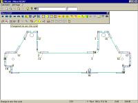
Cut contour cycle
• Part creation
To create a part, two modes are possible, depending on whether the order is "paper" or "file":
- collect parts from a CAD-CAM program as AUTOCAD and any file in standard format (DXF, IGES, etc.) ;
- use a local CAD program. that may create or modify parts very quickly. You define in TOLfab technological treatement functions : chamfer, loop, marking, micro-junctions, tool kind and cycles, in relation with the used technology, etc.
The part creation function also permits to enter or modify synthetically and quickly management elements : order description, machining contraints, delays, priorities, etc. The parts then defined are stored or not, according to the user's needs.

• Selection
It automatically defines, due to the data given by the machining management :
- prioritary choice : the program first places on the sheet prioritary parts, then the others in the holes ;
- list of the parts to be selected, in relation with the criteria defined by the user : delays (more or less urgent order), machining contraints (material, thickness, machine...), order description, etc.
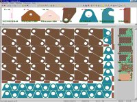
Nesting may be manual or automatic
• Nesting
From the selection, the program optimizes the placement of
the parts, whatever their number or their shape may be. The
number of sheets to be used is defined by TOLfab in relation
with the quantity of parts.The operator can use an already
existing nesting or complete a sheet already partially cut
that has been stored in memory.
There are three kinds of working to carry out a nesting:
- Manual nesting The user places the part as he wishes. He can make a rotation or place the part with a vertical or horizontal symmetry. TOLfab can validate the placement with regard or not to the inter-part and edge minimum distance. He can also choose a mode that allows the best possible readjustment of the part.
- Half-automatic nesting The user chooses a part. TOLfab places it in the best way.
- Automatic nesting TOLfab chooses the parts and places them in the best way on the sheet. The system is able to modify the placement mode according to the specific requests of each user.
These three methods may be mixed to get great flexibility and execution rapidity.
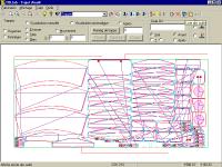
Tool path in case or machine with repositionning
• Tool path
It may be defined on the screen with two methods : manually or automatically.
- Automatic tool path The program computes the tool path for the parts to be cut. The operator can modify : pierce point, start point, input or output kind, an element of the tool path or the whole tool path.
- Manual tool path The operator can define : start point, cutting sense, clamp position, bridges between parts, etc. The tool path takes in account specificities of each kind of cutting : multi-torches in oxycutting, bridges in plasma, laser parameters, different cycles in nibbling, the choice of the tools in punching-nibbling, etc.
• Sheet management
This function permits to store the geometry of a sheet scrap. This scrap will then be used again to be a pattern for a new nesting.
• NC output
TOLfab automatically generates the program for the NC and transmits data by D.N.C. (Direct Numeric Command).
• Printed documentation
A shop documentation is printed. It contains a nesting design, a report of the placed parts, the times and cutting length, the scrap rate, etc.
|
|
|
|
|
|